SubsTech’s sister website Smooth Sliding provides independent engineering consulting services that help you to solve engine bearing related issues: failures, material selection, geometry design and optimization of hydrodynamic conditions.
Smooth Sliding is an engineering consulting company run by Dr. Dmitri Kopeliovich:

- VP R&D of King Engine Bearings.
- World leading expert (32 years of experience) in design, technology and materials for Engine bearings in applications such as automotive, renewable energy, aviation, racing and others.
- Founder and owner of SubsTech (Substances & Technologies) – a leading professional website on Materials Science and Engineering.
- Author of numerous scientific and engineering publications and patents.
- Founder and owner of Smooth Sliding.
For further information and for requesting consulting services please visit our sister website Smooth Sliding.
to Metals
to Engine bearings
Crush Height of Engine Bearings
Introduction
A rotating crankshaft takes the following actions on the engine bearings:
- Friction force in the rotation direction. Generally friction is hydrodynamic. It is generated by the oil separating the shaft and bearing surfaces. its value is determined by the rotation speed, oil viscosity, bearing load and bearing geometry. However, conditions of metal-to-metal contact are inevitable because of geometrical imperfections such as non-parallelism, shaft bending and misalignment. Direct contact (rubbing) produces friction force greater than hydrodynamic lubrication. Friction force acts to spin the bearing in the housing. The bearing spin is prevented due to the balancing effect of the counteracting friction force formed between the bearing back and housing surface.
- Heat generated by the friction. Both hydrodynamic friction and direct friction generate heat which is partially removed out of the bearing and partially absorbed by the bearing, housing and shaft. Heating affects the mechanical properties of the bearing material and oil viscosity. Hardness, strength and wear resistance of the bearing material decrease. Viscosity of the lubricant drops. Overheating may cause melting of the bearing overlay. Hot oil is prone to oxidation and thermal degradation. Heat generated by friction is extracted out from the bearing surface in two ways. Part of it is being taken by the oil flowing out of the bearing through the oil clearance gap. Another part is being transferred through the bearing back into its housing (connecting rod or engine block) and dissipating.
- Alternating loading. Cycling mode of combustion process in the internal combustion engines produces alternating character of the engine bearing loading. The load causes formation of stresses in the bearing wall and housing body and their distortions. In a loosely mounted bearing reciprocating tension-compression strain cycles may produce fretting effect (wear and scoring caused by oscillating contact) on the bearing back. Possible air gaps between the bearing back and housing surface cause flapping of the bearing wall which may lead to fatigue of the steel back material.
Bearing Press Fit
The adverse effects described in the previous section can be mitigated by proper fitting of the bearing in its housing.
The bearing back perimeter is always greater then the perimeter of the housing bore. In other words, the bearing outside diameter (OD) is greater than the bore diameter. Therefore, a bearing mounted in the housing is mechanically stressed and elastically compressed.
The difference between the bearing OD and bore diameter is called interference. Its value determines parameters of the bearing press fit.
Fig.1 depicts a bearing mounted in the housing.
The friction torque ML induced by the rotating shaft is balanced by the torque MH produced at the interface between the bearing back and bore surface. Counteracting of the two torques prevents spinning of the bearing. Elastic deformation of the bearing builds compression stress σ along the bearing wall.
Stress at the bearing-bore interface induces contact pressure P, which is normal to the bore surface.
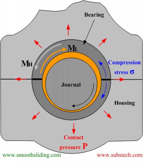
Fig.1 Condition of Press Fitted Bearing
A properly fitted bearing has uniform firm contact with the housing surface, which fulfills the following functions:
- Creates friction torque at the bearing back surface preventing bearing fretting and spinning in the housing;
- Provides maximum heat transfer out of the bearing through the bearing-housing interface;
- Increases the rigidity of the housing.
The value of contact pressure P required for reliable press fit of engine bearings depends on the bearing work conditions. Commonly it is not less than 8-10 MPa (1200-1500 psi).
Increasing contact pressure leads to an increase of the compression stress σ which may cause distortion of the bearing profile geometry at the joint zones in form of inward protrusion of the bearing material (Fig.2).
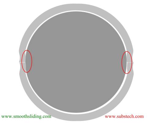
Fig.2 Distortion Caused by Too High Compression Stress
Depending on the application, the maximum value of compression stress σ, should not exceed 400-500 MPa (58,000-72,500 psi).
to top
Crush Height
There is no standard method of direct measurement of the bearing outside diameter or peripheral length . Instead a method of checking the bearing crush height is used.
Crush height is the difference between the outside circumferential length of a half bearing (one half shell) and half of the housing circumference measured at a certain press load.
Fig.3 and 4 illustrate a device for measuring crush height.
The tested bearing is installed in the gauge block and pressed with a predetermined force F producing compression stress σ=100 MPa. The force is calculated using formula:
F = 100*Acalc
Where:
F - applied force, N;
Acalc - cross-sectional area of bearing equivalent to bearing made of steel only, mm2;
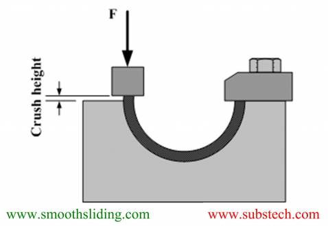
Fig.3 Measurement of Crush Height
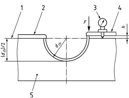
Fig.4 Measurement of Crush Height (ISO 3548-1)
The optimal value for crush height is dependent on the bearing diameter, housing material (modulus of elasticity and thermal expansion), housing dimensions and stricture (rigidity), and temperature.
The value of crush height not only determines compression stress σ and contact pressure P, but also affects the value of oil clearance. Greater crush height causes greater elastic expansion of the housing resulting in increase of oil clearance.
The effect of crush height, housing dimensions, material and temperature on the compression stress. contact pressure and oil clearance is illustrated in the following sections 4, 5 and 6.
to top
Effect of Housing Material
Housings of engine bearings are made of various materials such as steel, cast iron, aluminum or titanium.
The materials have different values of modulus of elasticity, Poisson’s ratio and coefficient of thermal expansion.
Therefore, a bearing having a particular value of the crush height induces different stress, contact pressure and oil clearance when fitted in identical housings but made of different materials.
Parameters of the bearings used in calculations are given in Table 1.
Crush height tolerance (difference between max. and min. limits) used in the calculations was 0.037 mm/1.5 thou.
Table 1 Input Parameters
| Housing material | Bearing material | Housing OD/ID | Housing ID, mm/inch | Shaft diameter, mm/inch | Bearing thickness, mm/inch | Bearing length, mm/inch | Temperature, ⁰C/ ⁰F | |||
| min. | max. | min. | max. | min. | max. | |||||
| Steel, Aluminum | Tri-metal | 1.5 | 50.180 / 1.9756 | 50.200 / 1.9763 | 46.958 / 1.8487 | 46.970 / 1.8492 | 1.588 / 0.0625 | 1.600 / 0.0630 | 15.0 / 0.591 | 20 / 68 |
The calculation results are presented in Fig.5-7.
Housing made of aluminum having modulus of elasticity ~1/3 of that of steel produces much lower compression stress at the same crush height (Fig.5). For example at crush height 0.1 mm/4 thou compression stress of the bearing wall is 350 MPa/50,750 psi in aluminum housing and 450 MPa/65,250 psi in steel housing.
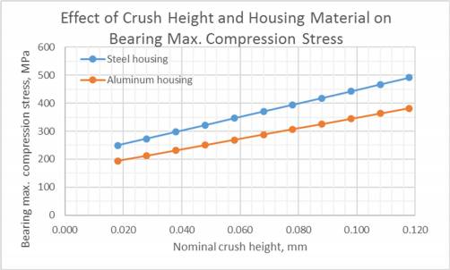
Fig.5
If required contact pressure is 10 MPa/1500 psi in steel housing it is achieved at crush height 0.06 mm/2.4 thou, whereas in aluminum housing crush height should be 0.082 mm/3.2 thou (Fig.6).
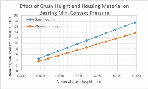
Fig.6
The difference in oil clearance in housings made of different materials reaches 20 µm/0.8 thou at crush height 0.100 mm/4 thou (Fig.7) - aluminum housing expands more than housing made of steel.
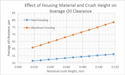
Fig.7
to top
Effect of Housing Rigidity
One of the factors affecting housing expansion is its rigidity or OD-to-ID ratio.
The higher the ratio the less housing deformation and the bearing stress and contact pressure (Fig.8-10).
The calculations were conducted for steel housing at OD-to-ID ratio varying between 1.25 to 2.0.
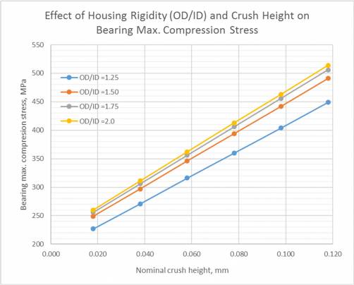
Fig.8
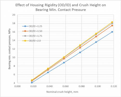
Fig.9
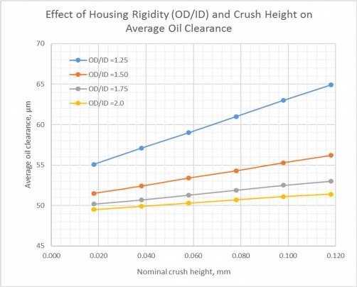
Fig.10
At OD/ID ratio equal or greater than 1.5 the stress parameters as well as the values of oil clearance are similar.
to top
Effect of Thermal Expansion and Wall Thickness
Engine bearings are made of steel-bronze or steel aluminum materials. However, effect of bronze or aluminum linings on the bearing thermal expansion is negligible. When temperature increases engine bearings expand according to the coefficient of thermal expansion of steel.
If the bearing housing is made of steel thermal effect on the press fit parameters and on the oil clearance is almost nil.
However, a bearing mounted in an aluminum housing is affected with heating.
Fig.11-13 depict thermal effect on press fit parameters for two bearings having different wall thickness 1.6 mm (0.063”) and 3 mm (0.118”). Crush height of the bearings was taken within the tolerance limits 0.100-0.137 mm (3.9-5.4 thou).
The input parameters of the calculations are presented in Table 2.
Table 2 Input Parameters
| Housing material | Bearing material | Housing OD/ID | Housing ID, mm/inch | Shaft diameter, mm/inch | Bearing thickness, mm/inch | Bearing length, mm/inch | Crush height, mm/inch | ||||
| min. | max. | min. | max. | min. | max. | min. | max. | ||||
| Aluminum | Tri-metal | 1.5 | 50.135 / 1.9738 | 50.155 / 1.9746 | 46.958 / 1.8487 | 46.970 / 1.8492 | 1.588 / 0.0625 | 1.600 / 0.0630 | 15.0 / 0.591 | 0.100/0.0039 | 0.137/0.0054 |
| Housing material | Bearing material | Housing OD/ID | Housing ID, mm/inch | Shaft diameter, mm/inch | Bearing thickness, mm/inch | Bearing length, mm/inch | Crush height, mm/inch | ||||
| min. | max. | min. | max. | min. | max. | min. | max. | ||||
| Aluminum | Tri-metal | 1.5 | 52.935 / 2.0841 | 52.955 / 2.0848 | 46.958 / 1.8487 | 46.970 / 1.8492 | 2.988 / 0.1176 | 3.000 / 0.1181 | 15.0 / 0.591 | 0.100/0.0039 | 0.137/0.0054 |
The bearing compression stress decreases by ~100 MPa/14,500 psi when the housing and bearing are heated from room temperature to 100 ⁰C/212 ⁰F (Fig.11).
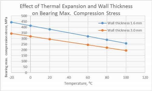
Fig.11
A bearing mounted in aluminum housing loses its press fit when heated. Contact pressure produced by the bearing with wall thickness 1.6 mm/0.063” is 13.5 MPa/2000 psi at room temperature, but it decreases to unacceptable level of 7 MPa/1000 psi at temperature 100 ⁰C/212 ⁰F (Fig.12).
More rigid bearing having wall thickness 3 mm/0.12” even heated to 100 ⁰C/212 ⁰F has minimum contact pressure 10 MPa/14,500 psi.
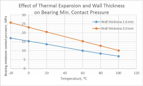
Fig.12
Thermal expansion of aluminum housing causes the oil clearance to increase (Fig.13). Oil clearance produced by the bearing with wall thickness 3 mm/0.12” is greater by 15-17 µm/0.59-0.67 thou than that produced by the bearing with wall thickness 1.6 mm/0.063”.
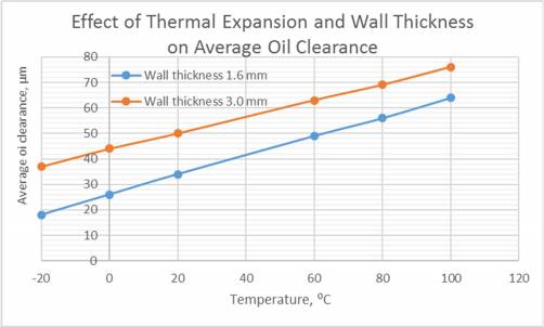
Fig.13
to top
Conclusions
- Actions of crankshaft on engine bearings are considered: friction force, heat, alternating loading.
- Mechanical stresses induced in a mounted bearing and at the bearing-housing interface as well as their effect on the bearing #PressFit are analyzed.
- The method of checking bearing crush height is described.
- Results of calculations of the effects of crush height, housing material, housing rigidity (OD/ID), temperature and bearing wall thickness on the compression stress, contact pressure and oil clearance are presented and discussed.
Related internal links
to Metals
to Engine bearings