Main page
About us
Sliding Bearings Consulting
Advertising Opportunities

SubsTech’s sister website Smooth Sliding provides independent engineering consulting services that help you to solve engine bearing related issues: failures, material selection, geometry design and optimization of hydrodynamic conditions.
Smooth Sliding is an engineering consulting company run by Dr. Dmitri Kopeliovich:
- VP R&D of King Engine Bearings.
- World leading expert (32 years of experience) in design, technology and materials for Engine bearings in applications such as automotive, renewable energy, aviation, racing and others.
- Founder and owner of SubsTech (Substances & Technologies) – a leading professional website on Materials Science and Engineering.
- Author of numerous scientific and engineering publications and patents.
- Founder and owner of Smooth Sliding.
For further information and for requesting consulting services please visit our sister website Smooth Sliding.
to Metals
to Engine bearings
Camshaft Bearings
Dr. Dmitri Kopeliovich
When speaking about engine bearings, we commonly focus on main and connecting rod bearings and the roles they play in crankshaft operation. Camshaft bearings are less loaded and generally have fewer problems. Therefore, innovative Engine bearing materials and new designs are mostly focused on crankshaft bearings, where probability of failure is greater.
However, camshaft bearings are also hydrodynamic bearings. They suffer from the same operational conditions as do crankshaft bearings: overloading, oil starvation, too thin minimum oil film, misalignment, and contaminated oil. The possible failures are also similar: material fatigue, excessive wear, seizure, and corrosion.
Bearings in camshaft mechanism
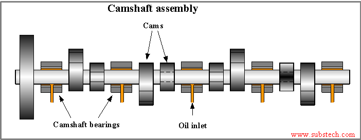
Camshaft bearings support the camshaft and provide for its rotation.
There are three possible configurations of camshaft mechanism:
- Overhead valve (OHV) designs
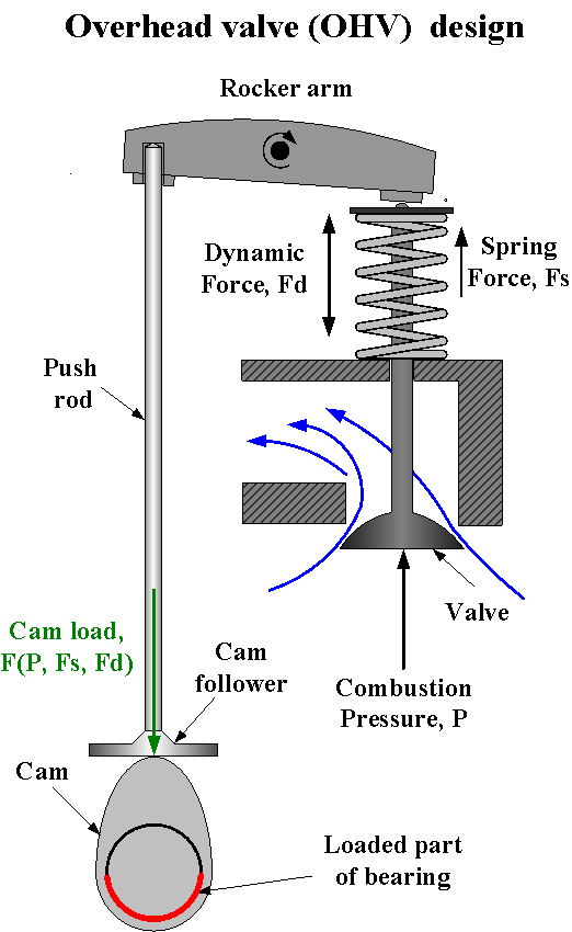
Overhead valve engines are also called pushrod engines. The camshaft of OHV is mounted in the cylinder block. The cams transmit the load through the pushrod to the rocker arm which presses the valve and displaces it from the closed position.
The force required for opening the valve counteracts the cylinder pressure, the spring force and the dynamic forces of the accelerating and decelerating (reciprocating) parts: valve, rocker arm, pushrod. Such force produces a load applied to the lower part of camshaft bearings. Thus, in the overhead valvetrain design, the lower part of the bearings may potentially fail.
However, at high rotation speed, the dynamic forces generated by the rotating cams may compensate for the load transmitted by the pushrods.
The inertia force of the cam may be expressed by the formula:
F = MC * ω2 * R
Where:
MC – eccentric mass of the cam;
ω – rotation speed;
R – eccentricity of the cam.
According to the formula, an increase of the rotation speed by three times raises the force by a factor of nine.
The dynamic forces produced by the rotating cams decrease the load applied to the lower parts of the bearings and create a load applied to the upper part.
The effect of the inertia force is very similar to that in main bearings of the crankshaft with its eccentric masses.
Overhead valve engines are commonly not commonly run at very high rotation speeds.
This limitation (up to 10,000 RPM) is caused by too high an inertia force produced by the relatively heavy reciprocating pushrods.
Greater rotation speeds may be achieved in the engines with an overhead camshaft design (OHC).
- Overhead camshaft (OHC) design with rocker arms
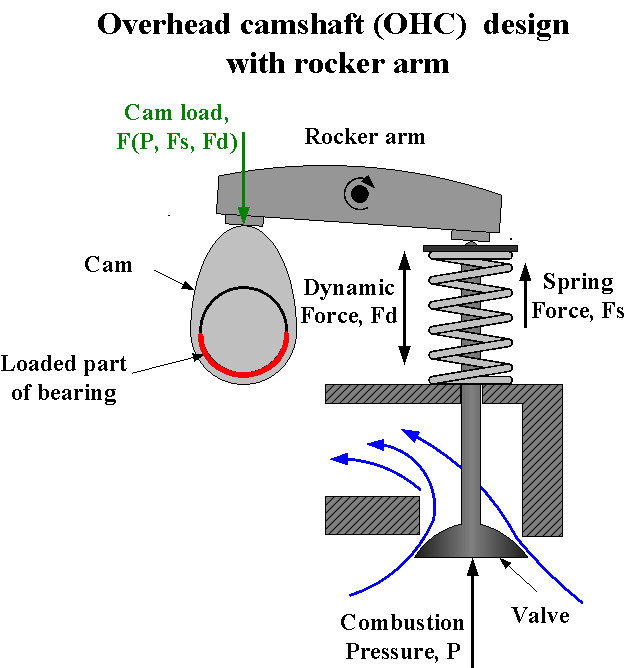
In OHC design, the camshaft is placed in the cylinder head.
The overhead camshaft configuration has two versions: single camshaft (SOHC) and double (twin) camshaft (DOHC).
The camshaft location in the OHC design with rocker arms is different from that in the overhead valve (OHV) mechanism. But the bearing loading is quite similar. The rocker arm is pushed when the cam lobe is in upper position. It means that the lower parts of the bearings are loaded. The load decreases with an increase of the rotation speed due to the inertia force of the rotating eccentric cam.
- Overhead camshaft (OHC) design with direct cam operation
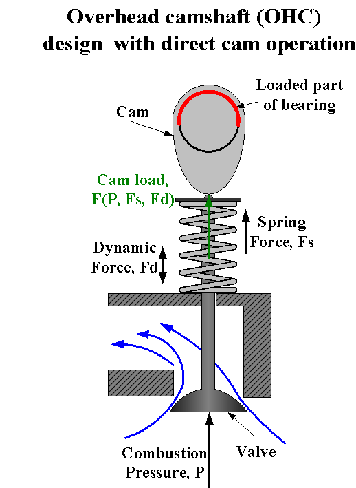
In this design, the cam presses the valve tappet directly without any intermediate rocker arm. Such configuration is principally different regarding the bearing loading.
The valve is pressed when the cam lobe is in the lower position; therefore the upper part of the bearing is loaded, in contrast to the designs with rocker arms.
Overhead camshaft design is used in high speed engines (up to 20,000 RPM) in which the dynamic (inertia) force developed by the cams is great and may cause considerable loading of the lower bearing parts.
to top
Characterization of camshaft bearings failures
High performance engines, diesel direct injection engines, turbo- and supercharged engines are characterized by increased loading of the bearings. The cylinder pressures are greater and the valve springs are stronger. Therefore the loads applied to the camshaft bearings are also higher than in conventional gasoline engines.
High load may cause two types of bearing failure:
- Fatigue of the lining (or overlay). If the load exceeds the fatigue strength of the lining, after a number of load cycles fatigue cracks form on the lining surface. The cracks propagate throughout the lining thickness, reach the steel-lining interface and continue to advance along the boundary with the steel back. Fragments of the lining detach from the steel surface.
Soft thick linings are prone to fatigue. An additional factor deteriorating the load capacity of camshaft bearings is the circumferential oil groove located in the bearing housing made of some engines. The groove decreases the effective area of contact between the bearing and the housing. The bearing material that is not- supported above the groove, strains under the alternating load and may fatigue.
- Excessive wear. Under high load the thickness of the oil film decreases. If the minimum oil film thickness is lower than the micro-asperities on the bearing and journal surfaces, the hydrodynamic lubrication is compromised and metal-to-metal contact between the surfaces is established. Direct friction results in fast wear of the bearing material.
Another factor causing camshaft bearing failure is misalignment. The bearing and the camshaft surfaces should be aligned when the camshaft is installed in the engine. However, distortions of the block induced by thermal or mechanical stresses cause misalignments of the bearings. Then some of the camshaft bearings start to operate in a constant metal-to-metal contact with the journal surface and their lining wears fast. The alignment of the distorted camshaft bearings housings may be reconditioned by oversize boring. Oversized OD camshaft bearings must be used in such engines.
Excessive wear of camshaft bearings may also be caused by oil starvation conditions at cold start of the engine. The oil path to the camshaft bearings is long in some engines. Therefore it takes some time for cold oil to reach the bearing surface. At each cold start the camshaft bearings operate in the absence of oil, causing metal-to-metal contact.
Oil starvation may be also a result from an excessive leakage of oil due to the large bearing clearance. In contrast to cold start, a reduction of the oil pump pressure caused by leakage occurs mostly with hot low viscosity oils.
Typical oil clearance of camshaft bearings is 0.0015-0.002*D
Where D – the bearing diameter.
to top
Structures and materials of camshaft bearings
The typical structures and designs of camshaft bearings are presented in the picture.
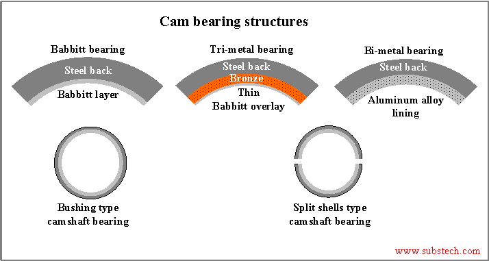
The most traditional design of camshaft bearings is a steel tube with a layer of lead based Babbitt alloy applied onto the inner surface (bush type camshaft bearing).
The bearings of this type may be supplied in semi-finished (un-bored) conditions. Then the bearings are bored after the installation in the engine. However, the precision (bored) finished type is more popular.
A relatively thick and soft Babbitt layer provides good conformability of the bearing. The material allows fitting its shape to misalignments. Babbitt has also has very good embeddability, which is important for bearings operating with contaminated oil.
The main disadvantage of Babbitt bearings is their low Fatigue strength (load capacity)load carrying capacity. Babbitt alloys are soft, therefore they have low fatigue strength. Also, the level of fatigue limit of the lining is strongly directly dependent on its thickness: the thicker the layer the lower its fatigue limit. Since the Babbitt lining is relatively thick, therefore its fatigue strength is low (~2,000 psi).
Bi-metallic camshaft bearings, with a lining made of aluminum alloy, have a much greater fatigue strength of at least 5,800 psi. The bearings are split shells type, rather than bush.
King Engine Bearings manufactures camshaft bearings made of silicon containing aluminum/silicon alloy: K-788. Their load capacity reaches 8,000 psi.
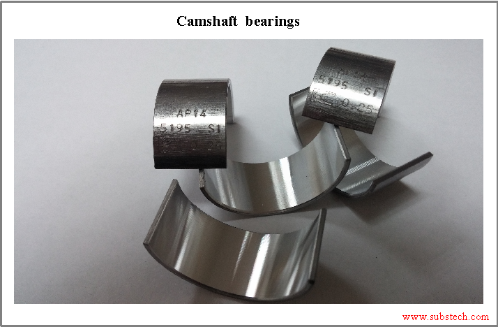
A bimetal structure with an aluminum alloy lining is the best solution for camshaft bearings. Aluminum alloy is not too hard, therefore it has good conformability. On the other hand it is stronger and more wear resistant than Babbitt.
In contrast to a tri-metal structure, the aluminum alloy bimetal bearings have superior conformability, and have can tolerate far greater wear no limitation on the amount of wear ssince they do not have an thin overlay. The thickness of the aluminum lining is approximately (~0.010”).
If the load applied to camshaft bearings exceeds the fatigue strength of aluminum alloys, tri-metal materials having a copper based intermediate layer and very thin (up to 0.0008”) soft babbitt overlay are used.
Tri-metal materials have greater load capacity, but their conformability and maximum wear are limited by the very low thickness of the overlay. Once the overlay is locally worn out and the bronze intermediate layer is exposed, seizure of the bearing by the steel journal becomes very probable. Since misalignments and excessive wear due to oil starvation are typical causes of camshaft bearing failures, tri-metal construction is rarely used in the design for fabrication of camshaft bearings.
to top
Related internal links
to Metals
to Engine bearings


